
Mechanical Polishing
Optical fibers are polished to eliminate the optical losses arising from the rough fiber endface. The optical losses such as scattering and back reflection could be eliminated by polishing the endface of the optical fiber. The most common polishing technique is the mechanical polishing. The surface roughness of the fiber endface is gradually descreased by using lapping films having different surface roughness. The lapping films are changed at every step to obtain smooth surface. Also, the fiber tip geometry is easily manipulated by mechanical polishing. The SEM images of the lapping films are represented in the Fig.1.

Fig.1: SEM images of the lapping films having roughness of (a) 30µm, (b) 9µm, (c) 3µm and (d) 0.3µm.
The surface roughness of the fiber endfaces are gradually decreased for every step. The fiber tip is polished at rough to fine lapping films orderly. The fiber surface images are shown in Fig.2. At the end of the polishing procedure a very smooth surface is obtained.
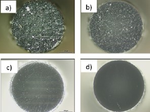
Fig.2: Optical microscope images (dark field) of the fiber endfaces polished at lapping films having roughness of (a) 30µm, (b) 9µm, (c) 3µm and (d) 0.3µm.

Fig.3: a) Optical microscope image of the fiber surface polished at 0.3µm lapping film. b) AFM image of the fiber surface polished at 0.3µm lapping film.
A very smooth surface could be achived at the final step of the mechanical polishing. In Fig.3a, the endface surface is represented. It is a very smooth surface and there isn’t any cracks or scracthes. In Fig.3b, AFM image of the Fig.3a is shown. The surface roughness is very low, and the average surface roughness is 1.17nm.
The fiber tip geometry is manipulated by polishing. The fiber tips having different geometries could be used in various applications. Flat-ended, side-firing, radial and double radial fiber tips are easily fabricated by mechanical polishing. Flat-ended fiber tip is used in laser systems, imaging, telecommunication and medical opereations. Before fabrication, the Zemax simulations were performed. The results are shown in the Fig.4. The flat-ended fiber is fabricated by mechanical polishing technique. The optical microscope images of the flat-ended fiber and its deflection are represented in Fig. 5.

Fig.4: Zemax simulation of the flat-ended fiber at non-sequential mode. a) Fiber geometry and light deflection from the tip. b) The light deflection shape from the flat-ended fiber at the rectangular detector.
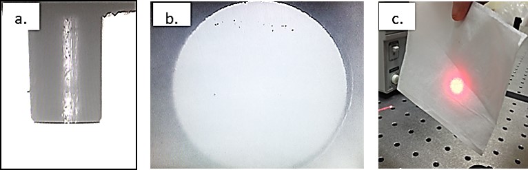
Fig.5: a) Optical microscope image of a) the fiber and b) its endface surface polished at 0.3µm lapping film. c) The deflection from the flat-ended fiber tip.
Side-firing Fiber Tip
Side-firing fiber optical probes are important tools in laser medicine. In the case of flat-ended fiber probes, light is transmitted as coupled out in the direction of the fiber. The deected light direction can be controlled by changing the fiber end-surface shape. Laser beam can be emitted almost perpendicular to the fiber axis thanks to the side-firing fiber probes. The main idea is that the laser beam can be localized onto the area that is desired to be ablated. It is very important to transmit almost full power of the laser perpendically, however, the light is coupled out from the fiber tip in three ways: leakage, deflection with leakage and perpendicularly deflection from the fiber tip. In order to reduce the leakage from the tip, the tip angle should be chosen specifically. It is desirable to fabricate a side-firing probe without any leakage. This is important for the medical applications since the laser beam leakage could damage healthy part of the tissue. The side-firing probes are used in the medical applications. They are suitable for the removal of tissue in hollow organs. These probes are desired for urology applications. Prostate tumors can be ablated thanks to side-firing probes. The side-firing fiber tips were designed and optimized by using Zemax. The optimum tip angle was calculated. The angle was chosen which deflects most of the incoming rays to the side of the fiber. The Zemax results are represented in Fig.6.
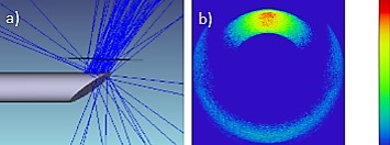
Fig.6: Zemax simulation of the side-firing fiber at non-sequential mode. a) Fiber geometry and light deflection from the tip. b) The light deflection shape from the side-firing fiber at the semi-spherical detector.
The fabricated side-firing probe tip geometry and deflection are shown in Fig.7.

Fig.7: a) Optical microscope image and b) deflection demonstration of the side-firing fiber tip.
Conical Fiber Tip – Radial Emitting Fiber
The direction of the laser beam can be controlled by forming the fiber tip with appropriate geometry. Conical tip fiber emits the light radially. The deflection of laser beam is 360° with homogeneous ring shape around the fiber tip. Radial (360°) emission is useful for many minimal invasive medical operations inside the tubular organs. The shape of output beam strongly depends on the tip angle. Cone tip angle should be determined according to the characteristics of both the fiber and the laser. The cone tip angle must provide that the laser power coupled into the fiber exits with minimum loss and that all the power should be localized into the ring shape emission, not the same direction along the fiber. The homogeneous ring shape laser emission provides homogeneous photothermal destruction inside the tubular organs, therefore, only the desired tissues are eliminated by laser ablation. The conical fiber tips were designed and optimized by using Zemax. The optimum tip angle was calculated. The Zemax results are represented in Fig.8.
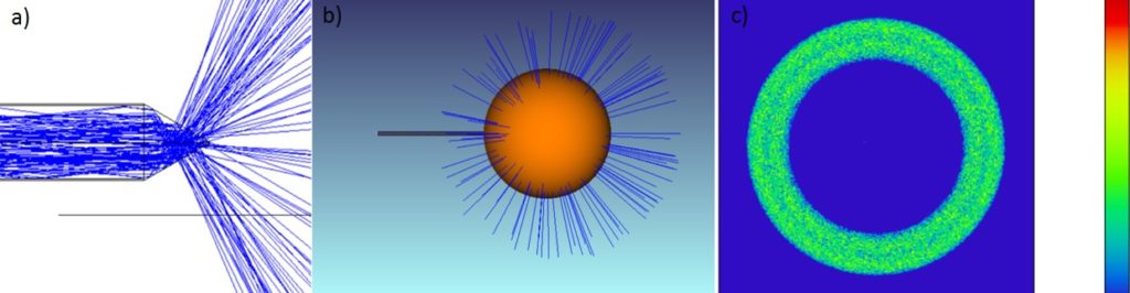
Fig.8: Zemax simulation of the conical tip fiber at non-sequential mode. a) Fiber geometry and light deflection from the tip. b) The radial emission from thefiber tip and c) the light deflection shape from the conical tip fiber at the semi-spherical detector.
The fabricated radial emitting probe tip geometry and deflection are shown in Fig.9.
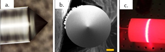
Fig.9: a) Optical microscope image and b) SEM image of the conical fiber tip. c) The deflection demonstration of the conical fiber tip.Laser Polishing
Laser polishing can be applied to the materials absorbing the radiation when 10.6µm CO2 laser is exposed. The main principle of laser polishing is that thin layer of a material melts for a while and cools down after radiation. The surface absorbing the radiation becomes smooth due to surface tension. In the silica-glass laser polishing process, low photon energy of the CO2 laser (0.2eV ) is not enough to brake Si-O bonds. The laser radiation is absorbed by surface and this energy is converted to thermal energy. For silica-glass material, the absorption is very high in that regime, in the order of 103 cm-1. The laser radiation is absorbed by a thin layer with a very small penetration depth inside the material. The temperature of the silica does not reach the glass transition temperature when exposed to CO2 laser since the energy is low. Therefore, glass is not transferred to the liquid state, it stays at viscoelastic region. Using this effect as an advantage, the glass surface could be fined by 10.6µm CO2 laser radiation. In Fig.10, the fiber endface optical microscope images taken at DIC mode are represented for before and after CO2 laser exposure. All the residual cracks and scratches could be eliminated by CO2 laser polishing.
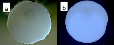
Fig.10: Optical microscope image of fiber endface a) polished at 0.3µm-lapping film and b) after polished with CO2 laser.